

Industrial electronic systems often operate for years in environments where downtime, unstable signals, or unexpected component failures can disrupt entire production processes. From factory automation and power control to industrial sensors and monitoring equipment, every application depends on printed circuit boards that deliver consistent electrical and mechanical performance. This makes industrial PCB manufacturing more demanding than simply producing a board that matches a design file. It requires careful material selection, reliable circuit construction, controlled manufacturing processes, and inspection methods suited to the product’s operating conditions.
For equipment manufacturers, understanding these requirements helps reduce design risks, improve product consistency, and select a PCB supplier capable of supporting long-term production.
1. What Makes Industrial PCB Manufacturing Different?
Industrial PCBs are used in equipment that may operate continuously, experience temperature fluctuations, or face electrical and mechanical stress. Unlike many consumer electronics applications, industrial systems often have longer service expectations and more demanding operating environments.
However, not every industrial PCB requires the same construction. A control board installed inside a temperature-regulated cabinet has different requirements from a motor-drive PCB exposed to heat, vibration, and electrical noise.
The manufacturing specification should therefore reflect the actual application rather than relying on a generic definition of an industrial-grade PCB.
Common Applications of Industrial PCBs
Industrial printed circuit boards are widely used in:
- Industrial automation: PLCs, motion controllers, robotic systems, and machine control units.
- Power electronics: Power supplies, inverters, motor drives, and energy management systems.
- Industrial monitoring: Temperature sensors, pressure monitoring systems, and data acquisition equipment.
- Communication equipment: Industrial Ethernet devices, gateways, and wireless communication modules.
- Process control: Equipment used in manufacturing, chemical processing, and production monitoring.
- Transportation and infrastructure: Control systems for rail equipment, traffic systems, and industrial infrastructure.
Each application places different demands on board materials, copper thickness, circuit layout, insulation, and quality verification.
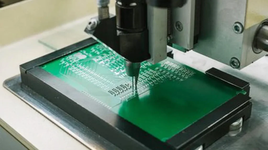
2. Key Reliability Requirements for Industrial PCBs
Reliable industrial PCB manufacturing starts with identifying the conditions that can affect board performance throughout its service life.
2.1 Thermal Stability and Heat Management
Industrial equipment may generate substantial heat through power components, high-current circuits, and continuous operation. Excessive temperatures can accelerate material aging, affect solder joint reliability, and increase the risk of electrical failure.
PCB designers and manufacturers should evaluate:
- Operating and peak temperature ranges.
- Heat generated by power components.
- Copper thickness and current-carrying requirements.
- Thermal vias and heat dissipation paths.
- Laminate glass transition temperature (Tg) and thermal decomposition characteristics.
- Board stack-up and copper distribution.
High-Tg FR-4 may be suitable for applications requiring improved thermal stability, while other laminate systems may be necessary for specialized electrical or environmental conditions. Material selection should be based on the actual thermal profile and fabrication requirements.
2.2 Mechanical Strength and Vibration Resistance
Industrial PCBs may be installed in motors, pumps, production machinery, and transportation equipment. These systems can expose circuit boards to vibration, shock, and repeated mechanical stress.
To improve mechanical reliability, manufacturers should consider:
- Appropriate board thickness and laminate construction.
- Balanced copper distribution and symmetrical stack-up where applicable.
- Secure connector and component mounting.
- Suitable mounting-hole locations and clearances.
- Reinforcement or mechanical support for heavy components.
- Board outline tolerances and dimensional stability.
For equipment exposed to continuous vibration, PCB reliability also depends on assembly design. Component placement, solder joint design, connector retention, and enclosure support should be evaluated together.
2.3 Electrical Performance and Insulation Reliability
Industrial control and power systems may contain high-current circuits, sensitive signal paths, and circuits operating at different voltage levels. Poor electrical design or manufacturing defects can lead to signal interference, excessive voltage drop, insulation breakdown, or short circuits.
Important manufacturing and design considerations include:
- Trace width and copper thickness based on current requirements.
- Adequate clearance and creepage distances where applicable.
- Controlled impedance for high-speed signal transmission.
- Reliable plated through-holes and via connections.
- Proper insulation between conductive layers.
- Consistent dielectric material properties.
For high-current applications, copper weight and conductor geometry should be calculated according to current, temperature rise, and operating conditions. For high-speed or noise-sensitive systems, impedance control, grounding strategy, and signal routing require additional attention.
2.4 Moisture, Dust, and Chemical Exposure
Industrial equipment may operate in workshops, outdoor installations, warehouses, or processing facilities. Humidity, dust, oil, and chemical contaminants can affect PCB insulation and conductive surfaces.
Possible protection measures include:
- Selecting suitable laminate and surface finish materials.
- Applying conformal coating when the application requires it.
- Using protective enclosures and appropriate sealing structures.
- Controlling board cleanliness and ionic contamination.
- Defining storage, handling, and packaging requirements.
Conformal coating can help protect assembled PCBs from moisture and contaminants, but it is not a substitute for proper enclosure design or environmental qualification. Coating material and process should be selected according to the expected exposure and maintenance conditions.
3. PCB Materials and Construction for Industrial Applications
Material selection directly affects thermal performance, electrical behavior, mechanical strength, and manufacturing consistency. The most suitable material depends on the board’s operating environment and functional requirements.
3.1 Choosing the Right PCB Substrate
FR-4 is widely used in industrial electronics because it offers a practical balance of electrical insulation, mechanical strength, availability, and cost. However, standard FR-4 is not automatically suitable for every industrial application.
| PCB Material | Key Characteristics | Typical Applications |
|---|---|---|
| Standard FR-4 | Balanced electrical and mechanical properties | Industrial controllers and general-purpose control boards |
| High-Tg FR-4 | Improved thermal stability for demanding processing and operating conditions | Power control and equipment exposed to elevated temperatures |
| High-frequency laminate | Controlled dielectric properties and signal performance | RF communication and high-frequency industrial systems |
| Metal-core PCB | Improved heat spreading through a metal base | LED power systems and selected thermal-management applications |
| Flexible PCB materials | Support bending and compact interconnection structures | Moving assemblies and space-constrained equipment |
Material specifications should include the required thickness, copper weight, dielectric properties, thermal characteristics, and compatibility with the intended manufacturing process.
3.2 Copper Thickness and Current-Carrying Capacity
Copper thickness is an important consideration for industrial PCBs, especially in power electronics and motor-control applications.
Common copper weights include 1 oz and 2 oz, while higher copper weights may be specified for applications with greater current requirements. However, increasing copper thickness alone does not guarantee better electrical or thermal performance.
The design should also consider:
- Trace width and length.
- Allowable temperature rise.
- Current load and duty cycle.
- Board thickness and layer arrangement.
- Heat dissipation and surrounding components.
- Manufacturing capability and etching tolerances.
For high-current circuits, the PCB manufacturer should review copper thickness and trace geometry during the design-for-manufacturing process.
3.3 Multilayer PCB Stack-Up and Signal Integrity
Many industrial systems combine power circuits, control logic, communication interfaces, and sensitive analog signals. A multilayer PCB can provide dedicated signal, ground, and power layers to improve routing efficiency and electrical performance.
A well-planned stack-up can help:
- Reduce electromagnetic interference.
- Provide more consistent return-current paths.
- Support controlled impedance.
- Separate sensitive signals from noisy power circuits.
- Improve routing density without compromising design requirements.
The layer count should be determined by circuit complexity, electrical performance, mechanical constraints, and production cost. Adding layers without a clear design need can increase manufacturing complexity and expense.
4. Critical Manufacturing Processes That Affect PCB Reliability
Even a well-designed PCB can fail if critical manufacturing processes are not properly controlled. Industrial PCB manufacturing requires consistency across material preparation, drilling, lamination, plating, imaging, etching, and surface finishing.
4.1 Drilling and Plated Through-Hole Quality
Drilled holes create the physical openings needed for component mounting and electrical interconnection. In multilayer boards, plated through-holes connect copper layers through conductive plating on the hole walls.
Potential problems include:
- Hole-wall damage.
- Poor copper plating coverage.
- Plating voids.
- Misalignment between drilled holes and internal pads.
- Insufficient annular ring.
Manufacturers should control drilling parameters, hole preparation, desmear, and copper plating. For demanding multilayer designs, process qualification and appropriate test coupons can help verify interconnection quality.
4.2 Lamination and Layer-to-Layer Registration
Multilayer PCBs are built by bonding copper-clad cores and prepreg materials under controlled heat and pressure.
Lamination quality affects:
- Bond strength between layers.
- Layer registration.
- Board thickness consistency.
- Internal insulation.
- Resistance to delamination.
Poor material handling, unsuitable lamination parameters, or unbalanced construction may contribute to defects such as voids, delamination, or board warpage.
A balanced stack-up and controlled lamination process are especially important for multilayer boards with tight dimensional and electrical requirements.
4.3 Etching, Trace Geometry, and Solder Mask
Etching defines the copper circuit pattern. Variations in etching can affect trace width, spacing, and conductor integrity.
For industrial PCBs, manufacturers should pay attention to:
- Trace width and spacing tolerances.
- Copper undercut and over-etching.
- Fine-pitch pattern accuracy.
- Solder mask registration.
- Coverage around pads and exposed copper areas.
The solder mask protects selected copper areas and helps prevent unintended solder bridging during assembly. Its material, adhesion, registration, and curing process should meet the requirements of the board design.
4.4 Surface Finish Selection
PCB surface finish protects exposed copper and supports solderability, electrical contact, or other application-specific needs.
Common options include:
| Surface Finish | Main Characteristics | Typical Considerations |
|---|---|---|
| HASL | Economical and widely used | Surface flatness may be less suitable for some fine-pitch components |
| Lead-Free HASL | Lead-free solderable finish | Process temperature and surface uniformity need consideration |
| ENIG | Flat surface and good oxidation resistance | Suitable for fine-pitch assembly; process quality must be controlled |
| OSP | Thin organic protective coating | Requires suitable storage and assembly handling |
| Immersion Silver | Flat solderable surface | Sensitive to storage and handling conditions |
No surface finish is universally best for industrial applications. Selection should consider component pitch, assembly process, contact requirements, storage conditions, and cost.
5. Quality Control and Testing in Industrial PCB Manufacturing
Quality assurance should cover both manufacturing prevention and product verification. Visual inspection alone cannot identify every internal or electrical defect.
A reliable quality plan combines process monitoring, inspection, electrical testing, and application-specific verification.
5.1 Visual and Dimensional Inspection
Visual inspection helps identify visible manufacturing issues, including:
- Scratches and contamination.
- Solder mask defects.
- Copper exposure in unintended areas.
- Surface finish irregularities.
- Board-edge damage.
- Marking and identification errors.
Dimensional inspection verifies board outline, thickness, hole position, and other drawing requirements. These checks are important when PCBs must fit precisely into industrial enclosures or mechanical assemblies.
5.2 Electrical Testing
Electrical testing helps verify that the fabricated PCB matches the intended circuit connectivity.
Common methods include:
- Continuity testing: Checks whether required conductive paths are connected.
- Isolation testing: Checks for unintended electrical connections between isolated nets.
- Impedance testing: Verifies specified impedance on controlled-impedance structures.
- High-potential testing: Used when required by the design or product specification to evaluate insulation performance.
The test method and acceptance limits should be defined according to the PCB design, applicable specifications, and intended application.
5.3 Internal Structure Inspection
For multilayer PCBs and other demanding constructions, internal defects may not be visible from the board surface.
Depending on the risk level and specification, manufacturers may use:
- Microsection analysis to examine plated hole walls and internal structures.
- X-ray inspection for selected internal features.
- Test coupons to evaluate plating and material performance.
- Thermal stress or other qualification tests where required.
These methods provide additional evidence of manufacturing quality, especially when internal interconnections are critical to product reliability.
5.4 Environmental and Reliability Testing
Industrial PCB qualification should reflect the product’s real operating environment. Depending on the application, relevant tests may include:
- Thermal cycling.
- Thermal shock.
- Temperature and humidity exposure.
- Vibration and mechanical shock.
- Solderability testing.
- Insulation resistance testing.
Not every PCB needs every test. The test plan should be based on operating temperature, humidity, vibration, electrical stress, expected service life, and customer requirements.
6. Understanding IPC Standards for Industrial PCB Quality
IPC standards provide a common technical framework for PCB design, fabrication, and assembly. They help manufacturers and customers define requirements, but simply stating “IPC compliant” does not fully describe a product’s quality expectations.
Different standards address different stages of the process.
| Standard | Main Focus | Relevance to Industrial PCB Projects |
|---|---|---|
| IPC-2221 | Generic PCB design requirements | Supports design rules and layout planning |
| IPC-6011 | Generic performance specification for printed boards | Provides a general performance framework |
| IPC-6012 | Qualification and performance requirements for rigid PCBs | Defines requirements for rigid board fabrication |
| IPC-A-600 | Acceptability of printed boards | Supports bare-board inspection and acceptance |
| IPC-A-610 | Acceptability of electronic assemblies | Applies to assembled electronic products |
6.1 Selecting the Appropriate PCB Class
IPC product classes describe different levels of performance and reliability expectations:
- Class 1: General electronic products where the main requirement is the function of the completed assembly.
- Class 2: Dedicated-service electronic products where continued performance and extended service life are important.
- Class 3: High-performance or high-reliability products where continued operation or operation on demand is critical.
The appropriate class should be agreed between the customer and manufacturer according to the product’s function, risk, and applicable specification. Class 3 should not be selected automatically for every industrial PCB, nor should it be treated as a substitute for application-specific requirements.
7. How to Choose an Industrial PCB Manufacturing Supplier
Choosing a PCB supplier involves more than comparing unit prices. Manufacturers should evaluate whether a supplier can consistently meet technical requirements and provide reliable production support.
7.1 Evaluate Manufacturing Capabilities
Before placing an order, confirm whether the supplier can support the required:
- Board dimensions and thickness.
- Layer count and stack-up.
- Copper weight.
- Minimum trace width and spacing.
- Drill sizes and via structures.
- Surface finishes.
- Controlled impedance requirements.
- Special materials and fabrication processes.
These capabilities should be verified against the actual design rather than relying only on a general equipment or capability list.
7.2 Review Quality Management and Traceability
A capable industrial PCB manufacturer should have documented quality procedures and appropriate inspection records.
Useful items to review include:
- Material specifications and batch identification.
- Production and inspection records.
- Electrical test reports.
- Process control procedures.
- Nonconformance handling and corrective actions.
- Lot traceability and change management.
For long-term industrial programs, consistent materials and controlled process changes are particularly important.
7.3 Confirm Engineering Support and DFM Review
Design-for-manufacturing (DFM) review helps identify potential production issues before fabrication begins.
A supplier should be able to review:
- Gerber or other accepted fabrication data.
- Drill files and board outlines.
- Stack-up and material requirements.
- Copper balance and layer registration.
- Impedance requirements.
- Critical tolerances and special notes.
Early engineering communication can reduce avoidable revisions, production delays, and quality risks.
7.4 Compare Total Project Value, Not Only Unit Cost
The lowest quotation may not represent the lowest total cost. Material substitutions, inconsistent quality, poor documentation, and repeated production issues can increase project expenses.
When comparing industrial PCB manufacturing suppliers, consider:
- Material and process consistency.
- First-pass yield and defect management.
- Lead time and production capacity.
- Engineering response and DFM support.
- Inspection and test coverage.
- Packaging and logistics requirements.
- Support for repeat orders and product lifecycle changes.
A supplier evaluation should balance price, technical capability, quality evidence, and long-term production stability.
8. Information to Prepare Before Requesting an Industrial PCB Quote
Providing complete technical information helps a manufacturer assess feasibility and prepare a more accurate quotation.
A typical PCB manufacturing package includes:
- Gerber files or other accepted fabrication data.
- Excellon drill files.
- PCB dimensions and thickness.
- Layer count and stack-up requirements.
- Copper weight for each layer.
- Material type and any specified Tg or dielectric requirements.
- Surface finish and solder mask color.
- Controlled impedance requirements, if applicable.
- Required IPC class or customer-specific acceptance criteria.
- Quantity, delivery schedule, and testing requirements.
For specialized industrial applications, also provide operating temperature, voltage and current conditions, environmental exposure, and any relevant reliability targets.
The more clearly these requirements are documented, the easier it is for the supplier to identify manufacturing risks and recommend a suitable production approach.
Conclusion: Reliability Starts with the Right Manufacturing Requirements
Reliable industrial PCB manufacturing depends on the alignment of design, materials, fabrication processes, inspection, and application-specific testing. Thermal stability, mechanical strength, electrical performance, and environmental protection should be evaluated according to the actual conditions in which the electronic system will operate.
For industrial equipment manufacturers, the most effective approach is to define performance requirements early, conduct DFM reviews before production, select appropriate materials and construction methods, and establish clear acceptance criteria with the PCB supplier. IPC standards can support this process, but project drawings and agreed specifications must define the requirements that matter.
By treating PCB reliability as a complete manufacturing and quality-control process, rather than a single material choice or inspection step, manufacturers can build a stronger foundation for consistent industrial electronic systems.
If you are developing a custom industrial PCB, share your design files, board specifications, and application requirements with STG to discuss manufacturing feasibility and a suitable production solution.